
Since we finally got a module working, I have now published the PCB design files under
- System reproduction
Basic embedded software for the new modules is already available on sourceforge. However, significant updates, especially to the wireless interface, is expected in the near future. The STL-files for the casing I will publish as soon as it has gone through some more iterations.
By the way, the new boards goes under the name MIMU22BTv2 (MIMU=multi-IMU, 22=number of IMUs on front and back, BT=Bluetooth, v2=version 2). This is how it’s referred to in all config-files in the software.
Note that for some feature such as the memory and the pressure sensor there is still no software support for and they have not been tested at all. On the other hand they are not necessary for the core functionality or the boards, i.e. pedestrian tracking.


 OpenShoe is an open source project for creating an embedded foot-mounted
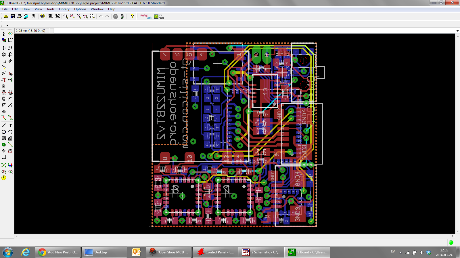